esp32_cam 读取和处理图像
esp32_cam read and process image
我正在尝试在 esp32_cam 上使用 tensorflow-lite 对图像进行分类。
我定义了以下我需要解决的子任务:
- 拍照
- 将照片尺寸缩小到(例如)28x28 像素灰度
- 运行 使用经过训练的模型进行推理
现在我卡在第 1 点和第 2 点之间,无法解决。
到目前为止我做了什么:
我使用 esp_camera_fb_get() 将图像保存到缓冲区中。之后,我将缓冲区中的值放入二维数组中。
然而,当我打印出其中一些值时,它们永远不会变成 0 或 255,即使我覆盖了整个镜头或将明亮的光源靠近它。
我有四个问题:
- 如何正确记录图像?
- 如何将其转换为二维数组?
- 如何将尺寸从(例如)160x120 缩小到 28x28?
- 我怎样才能正确地
Serial.print() 每个像素值来复制值并在我的计算机上绘制它们(例如使用 python matplotlib)
#define CAMERA_MODEL_AI_THINKER
 #include <esp_camera.h>
 #include "camera_pins.h"

 #define FRAME_SIZE FRAMESIZE_QQVGA
 #define WIDTH 160
 #define HEIGHT 120

 uint16_t img_array [HEIGHT][WIDTH] = { 0 };


 bool setup_camera(framesize_t);
 void frame_to_array(camera_fb_t * frame);
 void print_image_shape(camera_fb_t * frame);
 bool capture_image();

 void setup() {
     Serial.begin(115200);
     Serial.println(setup_camera(FRAME_SIZE) ? "OK" : "ERR INIT");
 }

 void loop() {
     if (!capture_image()) {
         Serial.println("Failed capture");
         delay(2000);

         return;
     }

     //print_features();
     delay(3000);
 }


 bool setup_camera(framesize_t frameSize) {
     camera_config_t config;

     config.ledc_channel = LEDC_CHANNEL_0;
     config.ledc_timer = LEDC_TIMER_0;
     config.pin_d0 = Y2_GPIO_NUM;
     config.pin_d1 = Y3_GPIO_NUM;
     config.pin_d2 = Y4_GPIO_NUM;
     config.pin_d3 = Y5_GPIO_NUM;
     config.pin_d4 = Y6_GPIO_NUM;
     config.pin_d5 = Y7_GPIO_NUM;
     config.pin_d6 = Y8_GPIO_NUM;
     config.pin_d7 = Y9_GPIO_NUM;
     config.pin_xclk = XCLK_GPIO_NUM;
     config.pin_pclk = PCLK_GPIO_NUM;
     config.pin_vsync = VSYNC_GPIO_NUM;
     config.pin_href = HREF_GPIO_NUM;
     config.pin_sscb_sda = SIOD_GPIO_NUM;
     config.pin_sscb_scl = SIOC_GPIO_NUM;
     config.pin_pwdn = PWDN_GPIO_NUM;
     config.pin_reset = RESET_GPIO_NUM;
     config.xclk_freq_hz = 20000000;
     config.pixel_format = PIXFORMAT_GRAYSCALE;
     config.frame_size = frameSize;
     config.jpeg_quality = 12;
     config.fb_count = 1;

     bool ok = esp_camera_init(&config) == ESP_OK;

     sensor_t *sensor = esp_camera_sensor_get();
     sensor->set_framesize(sensor, frameSize);

     return ok;
 }


 bool capture_image() {

     camera_fb_t * frame = NULL;
     frame = esp_camera_fb_get();

     print_image_shape(frame);

     frame_to_array(frame);

     esp_camera_fb_return(frame);

     if (!frame)
         return false;

     return true;
 }


 void print_image_shape(camera_fb_t * frame){

     // print shape of image and total length (=heigth*width)
     Serial.print("Width: ");
     Serial.print(frame->width);
     Serial.print("\tHeigth: ");
     Serial.print(frame->height);
     Serial.print("\tLength: ");
     Serial.println(frame->len);
 }

 void frame_to_array(camera_fb_t * frame){

     int len = frame->len;
     char imgBuffer[frame->len];
     int counter = 0;

     uint16_t img_array [HEIGHT][WIDTH] = { 0 };

     int h_counter = 0;
     int w_counter = 0;

     // write values from buffer into 2D Array
     for (int h=0; h < HEIGHT; h++){
         //Serial.println(h);
         for (int w=0; w < WIDTH; w++){
             //Serial.println(w);
             int position = h*(len/HEIGHT)+w;

             //Serial.println(position);
             img_array[h][w] = {frame->buf[position]};

             //Serial.print(img_array[h][w]);
             //Serial.print(",");
             //delay(2);
         }
     }


     //Serial.println("Current frame:");

     Serial.println("=====================");

 }
camera_pin.h:
#if defined(CAMERA_MODEL_WROVER_KIT)
#define PWDN_GPIO_NUM    -1
#define RESET_GPIO_NUM   -1
#define XCLK_GPIO_NUM    21
#define SIOD_GPIO_NUM    26
#define SIOC_GPIO_NUM    27

#define Y9_GPIO_NUM      35
#define Y8_GPIO_NUM      34
#define Y7_GPIO_NUM      39
#define Y6_GPIO_NUM      36
#define Y5_GPIO_NUM      19
#define Y4_GPIO_NUM      18
#define Y3_GPIO_NUM       5
#define Y2_GPIO_NUM       4
#define VSYNC_GPIO_NUM   25
#define HREF_GPIO_NUM    23
#define PCLK_GPIO_NUM    22

#elif defined(CAMERA_MODEL_ESP_EYE)
#define PWDN_GPIO_NUM    -1
#define RESET_GPIO_NUM   -1
#define XCLK_GPIO_NUM    4
#define SIOD_GPIO_NUM    18
#define SIOC_GPIO_NUM    23

#define Y9_GPIO_NUM      36
#define Y8_GPIO_NUM      37
#define Y7_GPIO_NUM      38
#define Y6_GPIO_NUM      39
#define Y5_GPIO_NUM      35
#define Y4_GPIO_NUM      14
#define Y3_GPIO_NUM      13
#define Y2_GPIO_NUM      34
#define VSYNC_GPIO_NUM   5
#define HREF_GPIO_NUM    27
#define PCLK_GPIO_NUM    25

#elif defined(CAMERA_MODEL_M5STACK_PSRAM)
#define PWDN_GPIO_NUM     -1
#define RESET_GPIO_NUM    15
#define XCLK_GPIO_NUM     27
#define SIOD_GPIO_NUM     25
#define SIOC_GPIO_NUM     23

#define Y9_GPIO_NUM       19
#define Y8_GPIO_NUM       36
#define Y7_GPIO_NUM       18
#define Y6_GPIO_NUM       39
#define Y5_GPIO_NUM        5
#define Y4_GPIO_NUM       34
#define Y3_GPIO_NUM       35
#define Y2_GPIO_NUM       32
#define VSYNC_GPIO_NUM    22
#define HREF_GPIO_NUM     26
#define PCLK_GPIO_NUM     21

#elif defined(CAMERA_MODEL_M5STACK_WIDE)
#define PWDN_GPIO_NUM     -1
#define RESET_GPIO_NUM    15
#define XCLK_GPIO_NUM     27
#define SIOD_GPIO_NUM     22
#define SIOC_GPIO_NUM     23

#define Y9_GPIO_NUM       19
#define Y8_GPIO_NUM       36
#define Y7_GPIO_NUM       18
#define Y6_GPIO_NUM       39
#define Y5_GPIO_NUM        5
#define Y4_GPIO_NUM       34
#define Y3_GPIO_NUM       35
#define Y2_GPIO_NUM       32
#define VSYNC_GPIO_NUM    25
#define HREF_GPIO_NUM     26
#define PCLK_GPIO_NUM     21

#elif defined(CAMERA_MODEL_AI_THINKER)
#define PWDN_GPIO_NUM     32
#define RESET_GPIO_NUM    -1
#define XCLK_GPIO_NUM      0
#define SIOD_GPIO_NUM     26
#define SIOC_GPIO_NUM     27

#define Y9_GPIO_NUM       35
#define Y8_GPIO_NUM       34
#define Y7_GPIO_NUM       39
#define Y6_GPIO_NUM       36
#define Y5_GPIO_NUM       21
#define Y4_GPIO_NUM       19
#define Y3_GPIO_NUM       18
#define Y2_GPIO_NUM        5
#define VSYNC_GPIO_NUM    25
#define HREF_GPIO_NUM     23
#define PCLK_GPIO_NUM     22

#else
#error "Camera model not selected"
#endif
我没有使用过 ESP32 摄像头,所以我不能谈论它,但我在 STM32 上做过类似的项目,所以我只能回答这个问题:
1。如何正确记录图像?
我在微控制器上设置相机时也遇到了问题,所以我和你的想法一样,通过串口将图像传回 PC。请参考第4点
2。如何将其转换为二维数组?
我怀疑您想这样做是为了将其复制到 tflite 微型模型输入缓冲区。如果是这样的话,你不需要!您可以将展平的一维图像数组写入模型输入缓冲区,因为这是 tflite micro 实际期望的:
uint8_t img_array[HEIGHT * WIDTH] = { 0 }; // grayscale goes from 0 to 255. fits in 8bits
TfLiteTensor* model_input = nullptr;
...
void setup(){
    ... // Create your tflite interpreter and rest of your code
    model_input = interpreter->input(0); // get model input pointer
}
void loop() {
    ...
    // tflite model has input shape [batch_size, height, width, channels]
    // which in turn is [1, HEIGHT, WIDTH, 1] one channel because I think you are
    // using grayscale images, otherwise 3(RGB)
    // but tflite micro expects flattened 1D array so you can just do this
    for (uint32_t i = 0; i < HEIGHT*WIDTH; i++){
        // Assuming your model input expects signed 8bit integers
        model_input->data.int8[i] = (int8_t) (img_array[i] - 128);
    }
}
EDIT:最后一行将 model_input 指针指向模型输入结构并访问其 data 成员(参见 this if you are not familiar with struct pointers in C). Then, since I assumed your model input data type is 8 bit signed integers, it accesses the data union with int8. If your model input data type were 32-bit floats you could have used model_input->data.f[i] for example. Here具有所有可用访问类型的源代码。在正确寻址模型输入缓冲区后,我们分配相应的 img_array 像素数据。由于像素数据的范围为 [0, 255],我们需要将其转换为有效的有符号数据8 位整数类型和范围,因此必须减去 128,得到 [-128, 127] 范围。
希望您明白了。如果您使用其他格式(如 RGB565),请告诉我,我会给您一个不同的代码段。
EDIT: 如果你是采集RGB图像,最常用的格式是RGB565,意思是每16位有一个像素数据(红色5个,绿色6个,绿色5个为蓝色)。这是一个片段,它将以该格式捕获的图像转换为 RGB888(这是您的模型可能期望的)并将其复制到模型输入缓冲区:
// NOTICE FRAME BUFFER IS NOW uint16_t to store each pixel
uint16_t img_array[HEIGHT * WIDTH] = { 0 };
TfLiteTensor* model_input = nullptr;
...
void setup(){
    ... // Create your tflite interpreter and rest of your code
    model_input = interpreter->input(0); // get model input pointer
}
void loop() {
    ...
    // Fill input buffer
    uint32_t input_ix = 0; // index for the model input

    // tflite model has input shape [batch_size, height, width, channels]
    // which in turn is [1, HEIGHT, WIDTH, 3] three channels because RGB
    // but tflite micro expects flattened 1D array so you can just do this
    for (uint32_t pix = 0; i < HEIGHT*WIDTH; pix++){
       // Convert from RGB55 to RGB888 and int8 range
       uint16_t color = img_array[pix];
       int16_t r = ((color & 0xF800) >> 11)*255/0x1F - 128;
       int16_t g = ((color & 0x07E0) >> 5)*255/0x3F - 128;
       int16_t b = ((color & 0x001F) >> 0)*255/0x1F - 128;

       model_input->data.int8[input_ix] =   (int8_t) r;
       model_input->data.int8[input_ix+1] = (int8_t) g;
       model_input->data.int8[input_ix+2] = (int8_t) b;

       input_ix += 3;
    }
}
Here 是 C 中从 RGB888 到 RGB565 的分步指南,我只是做了相反的操作。您可能已经注意到屏蔽掉颜色通道位后的乘法。以红色为例:一旦你屏蔽掉 (color & 0xF800) >> 11) 位,红色值将从 [0, (2^5)-1] 开始,但我们想要一个 [0, 255] 范围,所以我们除以那个数字( (2^5)-1 = 31 = 0x1F ) 并乘以 255,得到我们想要的范围。然后我们可以减去 128 以获得 [-128, 127] 带符号的 8 位范围。之前进行乘法是为了保持精度。蓝色通道是相同的,在绿色通道中,我们除以 (2^6)-1=63=0x3F 因为它有 6 位。
3。如何将大小从(例如)160x120 缩小到 28x28?
您可以在 C 中实现一个算法,但我采用了简单的方法:我在我已经训练好的模型中添加了一个预处理 lambda 层来执行此操作:
IMG_SIZE = (28, 28)

def lm_uc_preprocess(inputs):
    # 'nearest' is the ONLY method supported by tflite micro as of October 2020 as you can see in
    # https://github.com/tensorflow/tensorflow/blob/a1e5d73663152b0d7f0d9661e5d602b442acddba/tensorflow/lite/micro/all_ops_resolver.cc#L70
    res_imgs = tf.image.resize(inputs, IMG_SIZE, method='nearest')
    # Normalize to the range [-1,1] # (OPTIONAL)
    norm_imgs = res_imgs*(1/127.5) -1 # multiply by reciprocal of 127.5 as DIV is not supported by tflite micro
    return norm_imgs
EDIT: 大多数计算机视觉模型期望图像输入值范围为 [0, 1] 或 [-1, 1] 但像素值通常为 8 位,所以它们的范围是 [0, 255]。要 将它们的值标准化 到所需的范围 [a, b],我们可以应用以下公式:
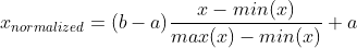
在我们的例子中,min(x)=0,max(x)=255,a=-1,b=1。因此,每个归一化值是 x_normalized = x_value/127.5 -1.
直观上你可以看到 255/127.5 -1 = 1,以及 0/255 -1 = -1。这就是 127.5 和 -1 值的来源。
现在您可以定义完整的模型:
capture_height, capture_width, channels = (160, 120, 1)

uc_final_model = keras.models.Sequential([
    keras.layers.InputLayer((capture_height, capture_width, channels), dtype=tf.float32),
    keras.layers.Lambda(lm_uc_preprocess), # (160, 120) to (28, 28)
    my_trained_model
])

# You should quantize your model parameters and inputs to int8 when compressing to tflite after this
这样,最终模型的输入形状等于相机捕获分辨率。这允许我复制图像数组,如第 2 点所示。
4。我怎样才能正确 Serial.print() 每个像素值来复制值并在我的计算机上绘制它们(例如使用 python matplotlib)
我尝试了一些方法,这对我有用:您可以尝试像这样打印值 123, 32, 1, 78, 90,(即用逗号分隔),这应该很容易做到。然后,如果您使用的是 Arduino,则可以使用 this cool program 来记录串行数据。如果您不使用 arduino,Putty 具有日志记录功能。然后你可以这样做:
with open("img_test.txt") as f:
    str_img_test = f.read()

img_test = np.array(str_img_test.split(",")[:-1], dtype=np.uint8)
img_test = img_test.reshape(160, 120)

plt.figure()
plt.imshow(img_test)
plt.axis('off')
plt.show()
捕获图像和保存日志的过程有点麻烦,但应该不会太令人沮丧,因为这只是为了调试是否正确捕获了图像。
这是一个非常笼统的问题,所以如果我遗漏了什么或者您想更深入地了解某些方面,请告诉我。
编辑
我已经 public(并开源)了我的完整代码和文档 on this repository,其中包含与您正在构建的应用程序非常相似的应用程序。此外,我还计划将计算机视觉示例移植到 ESP32。请注意存储库正在开发中并且会持续一段时间,尽管这个例子已经完成(待修订)。
我认为很多对微控制器上的深度学习感兴趣的人会发现存储库有趣且有用。
我正在尝试在 esp32_cam 上使用 tensorflow-lite 对图像进行分类。 我定义了以下我需要解决的子任务:
- 拍照
- 将照片尺寸缩小到(例如)28x28 像素灰度
- 运行 使用经过训练的模型进行推理
现在我卡在第 1 点和第 2 点之间,无法解决。
到目前为止我做了什么:
我使用 esp_camera_fb_get() 将图像保存到缓冲区中。之后,我将缓冲区中的值放入二维数组中。
然而,当我打印出其中一些值时,它们永远不会变成 0 或 255,即使我覆盖了整个镜头或将明亮的光源靠近它。
我有四个问题:
- 如何正确记录图像?
- 如何将其转换为二维数组?
- 如何将尺寸从(例如)160x120 缩小到 28x28?
- 我怎样才能正确地
Serial.print()每个像素值来复制值并在我的计算机上绘制它们(例如使用 python matplotlib)
#define CAMERA_MODEL_AI_THINKER
#include <esp_camera.h>
#include "camera_pins.h"
#define FRAME_SIZE FRAMESIZE_QQVGA
#define WIDTH 160
#define HEIGHT 120
uint16_t img_array [HEIGHT][WIDTH] = { 0 };
bool setup_camera(framesize_t);
void frame_to_array(camera_fb_t * frame);
void print_image_shape(camera_fb_t * frame);
bool capture_image();
void setup() {
Serial.begin(115200);
Serial.println(setup_camera(FRAME_SIZE) ? "OK" : "ERR INIT");
}
void loop() {
if (!capture_image()) {
Serial.println("Failed capture");
delay(2000);
return;
}
//print_features();
delay(3000);
}
bool setup_camera(framesize_t frameSize) {
camera_config_t config;
config.ledc_channel = LEDC_CHANNEL_0;
config.ledc_timer = LEDC_TIMER_0;
config.pin_d0 = Y2_GPIO_NUM;
config.pin_d1 = Y3_GPIO_NUM;
config.pin_d2 = Y4_GPIO_NUM;
config.pin_d3 = Y5_GPIO_NUM;
config.pin_d4 = Y6_GPIO_NUM;
config.pin_d5 = Y7_GPIO_NUM;
config.pin_d6 = Y8_GPIO_NUM;
config.pin_d7 = Y9_GPIO_NUM;
config.pin_xclk = XCLK_GPIO_NUM;
config.pin_pclk = PCLK_GPIO_NUM;
config.pin_vsync = VSYNC_GPIO_NUM;
config.pin_href = HREF_GPIO_NUM;
config.pin_sscb_sda = SIOD_GPIO_NUM;
config.pin_sscb_scl = SIOC_GPIO_NUM;
config.pin_pwdn = PWDN_GPIO_NUM;
config.pin_reset = RESET_GPIO_NUM;
config.xclk_freq_hz = 20000000;
config.pixel_format = PIXFORMAT_GRAYSCALE;
config.frame_size = frameSize;
config.jpeg_quality = 12;
config.fb_count = 1;
bool ok = esp_camera_init(&config) == ESP_OK;
sensor_t *sensor = esp_camera_sensor_get();
sensor->set_framesize(sensor, frameSize);
return ok;
}
bool capture_image() {
camera_fb_t * frame = NULL;
frame = esp_camera_fb_get();
print_image_shape(frame);
frame_to_array(frame);
esp_camera_fb_return(frame);
if (!frame)
return false;
return true;
}
void print_image_shape(camera_fb_t * frame){
// print shape of image and total length (=heigth*width)
Serial.print("Width: ");
Serial.print(frame->width);
Serial.print("\tHeigth: ");
Serial.print(frame->height);
Serial.print("\tLength: ");
Serial.println(frame->len);
}
void frame_to_array(camera_fb_t * frame){
int len = frame->len;
char imgBuffer[frame->len];
int counter = 0;
uint16_t img_array [HEIGHT][WIDTH] = { 0 };
int h_counter = 0;
int w_counter = 0;
// write values from buffer into 2D Array
for (int h=0; h < HEIGHT; h++){
//Serial.println(h);
for (int w=0; w < WIDTH; w++){
//Serial.println(w);
int position = h*(len/HEIGHT)+w;
//Serial.println(position);
img_array[h][w] = {frame->buf[position]};
//Serial.print(img_array[h][w]);
//Serial.print(",");
//delay(2);
}
}
//Serial.println("Current frame:");
Serial.println("=====================");
}
camera_pin.h:
#if defined(CAMERA_MODEL_WROVER_KIT)
#define PWDN_GPIO_NUM -1
#define RESET_GPIO_NUM -1
#define XCLK_GPIO_NUM 21
#define SIOD_GPIO_NUM 26
#define SIOC_GPIO_NUM 27
#define Y9_GPIO_NUM 35
#define Y8_GPIO_NUM 34
#define Y7_GPIO_NUM 39
#define Y6_GPIO_NUM 36
#define Y5_GPIO_NUM 19
#define Y4_GPIO_NUM 18
#define Y3_GPIO_NUM 5
#define Y2_GPIO_NUM 4
#define VSYNC_GPIO_NUM 25
#define HREF_GPIO_NUM 23
#define PCLK_GPIO_NUM 22
#elif defined(CAMERA_MODEL_ESP_EYE)
#define PWDN_GPIO_NUM -1
#define RESET_GPIO_NUM -1
#define XCLK_GPIO_NUM 4
#define SIOD_GPIO_NUM 18
#define SIOC_GPIO_NUM 23
#define Y9_GPIO_NUM 36
#define Y8_GPIO_NUM 37
#define Y7_GPIO_NUM 38
#define Y6_GPIO_NUM 39
#define Y5_GPIO_NUM 35
#define Y4_GPIO_NUM 14
#define Y3_GPIO_NUM 13
#define Y2_GPIO_NUM 34
#define VSYNC_GPIO_NUM 5
#define HREF_GPIO_NUM 27
#define PCLK_GPIO_NUM 25
#elif defined(CAMERA_MODEL_M5STACK_PSRAM)
#define PWDN_GPIO_NUM -1
#define RESET_GPIO_NUM 15
#define XCLK_GPIO_NUM 27
#define SIOD_GPIO_NUM 25
#define SIOC_GPIO_NUM 23
#define Y9_GPIO_NUM 19
#define Y8_GPIO_NUM 36
#define Y7_GPIO_NUM 18
#define Y6_GPIO_NUM 39
#define Y5_GPIO_NUM 5
#define Y4_GPIO_NUM 34
#define Y3_GPIO_NUM 35
#define Y2_GPIO_NUM 32
#define VSYNC_GPIO_NUM 22
#define HREF_GPIO_NUM 26
#define PCLK_GPIO_NUM 21
#elif defined(CAMERA_MODEL_M5STACK_WIDE)
#define PWDN_GPIO_NUM -1
#define RESET_GPIO_NUM 15
#define XCLK_GPIO_NUM 27
#define SIOD_GPIO_NUM 22
#define SIOC_GPIO_NUM 23
#define Y9_GPIO_NUM 19
#define Y8_GPIO_NUM 36
#define Y7_GPIO_NUM 18
#define Y6_GPIO_NUM 39
#define Y5_GPIO_NUM 5
#define Y4_GPIO_NUM 34
#define Y3_GPIO_NUM 35
#define Y2_GPIO_NUM 32
#define VSYNC_GPIO_NUM 25
#define HREF_GPIO_NUM 26
#define PCLK_GPIO_NUM 21
#elif defined(CAMERA_MODEL_AI_THINKER)
#define PWDN_GPIO_NUM 32
#define RESET_GPIO_NUM -1
#define XCLK_GPIO_NUM 0
#define SIOD_GPIO_NUM 26
#define SIOC_GPIO_NUM 27
#define Y9_GPIO_NUM 35
#define Y8_GPIO_NUM 34
#define Y7_GPIO_NUM 39
#define Y6_GPIO_NUM 36
#define Y5_GPIO_NUM 21
#define Y4_GPIO_NUM 19
#define Y3_GPIO_NUM 18
#define Y2_GPIO_NUM 5
#define VSYNC_GPIO_NUM 25
#define HREF_GPIO_NUM 23
#define PCLK_GPIO_NUM 22
#else
#error "Camera model not selected"
#endif
我没有使用过 ESP32 摄像头,所以我不能谈论它,但我在 STM32 上做过类似的项目,所以我只能回答这个问题:
1。如何正确记录图像?
我在微控制器上设置相机时也遇到了问题,所以我和你的想法一样,通过串口将图像传回 PC。请参考第4点
2。如何将其转换为二维数组?
我怀疑您想这样做是为了将其复制到 tflite 微型模型输入缓冲区。如果是这样的话,你不需要!您可以将展平的一维图像数组写入模型输入缓冲区,因为这是 tflite micro 实际期望的:
uint8_t img_array[HEIGHT * WIDTH] = { 0 }; // grayscale goes from 0 to 255. fits in 8bits
TfLiteTensor* model_input = nullptr;
...
void setup(){
... // Create your tflite interpreter and rest of your code
model_input = interpreter->input(0); // get model input pointer
}
void loop() {
...
// tflite model has input shape [batch_size, height, width, channels]
// which in turn is [1, HEIGHT, WIDTH, 1] one channel because I think you are
// using grayscale images, otherwise 3(RGB)
// but tflite micro expects flattened 1D array so you can just do this
for (uint32_t i = 0; i < HEIGHT*WIDTH; i++){
// Assuming your model input expects signed 8bit integers
model_input->data.int8[i] = (int8_t) (img_array[i] - 128);
}
}
EDIT:最后一行将 model_input 指针指向模型输入结构并访问其 data 成员(参见 this if you are not familiar with struct pointers in C). Then, since I assumed your model input data type is 8 bit signed integers, it accesses the data union with int8. If your model input data type were 32-bit floats you could have used model_input->data.f[i] for example. Here具有所有可用访问类型的源代码。在正确寻址模型输入缓冲区后,我们分配相应的 img_array 像素数据。由于像素数据的范围为 [0, 255],我们需要将其转换为有效的有符号数据8 位整数类型和范围,因此必须减去 128,得到 [-128, 127] 范围。
希望您明白了。如果您使用其他格式(如 RGB565),请告诉我,我会给您一个不同的代码段。
EDIT: 如果你是采集RGB图像,最常用的格式是RGB565,意思是每16位有一个像素数据(红色5个,绿色6个,绿色5个为蓝色)。这是一个片段,它将以该格式捕获的图像转换为 RGB888(这是您的模型可能期望的)并将其复制到模型输入缓冲区:
// NOTICE FRAME BUFFER IS NOW uint16_t to store each pixel
uint16_t img_array[HEIGHT * WIDTH] = { 0 };
TfLiteTensor* model_input = nullptr;
...
void setup(){
... // Create your tflite interpreter and rest of your code
model_input = interpreter->input(0); // get model input pointer
}
void loop() {
...
// Fill input buffer
uint32_t input_ix = 0; // index for the model input
// tflite model has input shape [batch_size, height, width, channels]
// which in turn is [1, HEIGHT, WIDTH, 3] three channels because RGB
// but tflite micro expects flattened 1D array so you can just do this
for (uint32_t pix = 0; i < HEIGHT*WIDTH; pix++){
// Convert from RGB55 to RGB888 and int8 range
uint16_t color = img_array[pix];
int16_t r = ((color & 0xF800) >> 11)*255/0x1F - 128;
int16_t g = ((color & 0x07E0) >> 5)*255/0x3F - 128;
int16_t b = ((color & 0x001F) >> 0)*255/0x1F - 128;
model_input->data.int8[input_ix] = (int8_t) r;
model_input->data.int8[input_ix+1] = (int8_t) g;
model_input->data.int8[input_ix+2] = (int8_t) b;
input_ix += 3;
}
}
Here 是 C 中从 RGB888 到 RGB565 的分步指南,我只是做了相反的操作。您可能已经注意到屏蔽掉颜色通道位后的乘法。以红色为例:一旦你屏蔽掉 (color & 0xF800) >> 11) 位,红色值将从 [0, (2^5)-1] 开始,但我们想要一个 [0, 255] 范围,所以我们除以那个数字( (2^5)-1 = 31 = 0x1F ) 并乘以 255,得到我们想要的范围。然后我们可以减去 128 以获得 [-128, 127] 带符号的 8 位范围。之前进行乘法是为了保持精度。蓝色通道是相同的,在绿色通道中,我们除以 (2^6)-1=63=0x3F 因为它有 6 位。
3。如何将大小从(例如)160x120 缩小到 28x28?
您可以在 C 中实现一个算法,但我采用了简单的方法:我在我已经训练好的模型中添加了一个预处理 lambda 层来执行此操作:
IMG_SIZE = (28, 28)
def lm_uc_preprocess(inputs):
# 'nearest' is the ONLY method supported by tflite micro as of October 2020 as you can see in
# https://github.com/tensorflow/tensorflow/blob/a1e5d73663152b0d7f0d9661e5d602b442acddba/tensorflow/lite/micro/all_ops_resolver.cc#L70
res_imgs = tf.image.resize(inputs, IMG_SIZE, method='nearest')
# Normalize to the range [-1,1] # (OPTIONAL)
norm_imgs = res_imgs*(1/127.5) -1 # multiply by reciprocal of 127.5 as DIV is not supported by tflite micro
return norm_imgs
EDIT: 大多数计算机视觉模型期望图像输入值范围为 [0, 1] 或 [-1, 1] 但像素值通常为 8 位,所以它们的范围是 [0, 255]。要 将它们的值标准化 到所需的范围 [a, b],我们可以应用以下公式:
在我们的例子中,min(x)=0,max(x)=255,a=-1,b=1。因此,每个归一化值是 x_normalized = x_value/127.5 -1.
直观上你可以看到 255/127.5 -1 = 1,以及 0/255 -1 = -1。这就是 127.5 和 -1 值的来源。
现在您可以定义完整的模型:
capture_height, capture_width, channels = (160, 120, 1)
uc_final_model = keras.models.Sequential([
keras.layers.InputLayer((capture_height, capture_width, channels), dtype=tf.float32),
keras.layers.Lambda(lm_uc_preprocess), # (160, 120) to (28, 28)
my_trained_model
])
# You should quantize your model parameters and inputs to int8 when compressing to tflite after this
这样,最终模型的输入形状等于相机捕获分辨率。这允许我复制图像数组,如第 2 点所示。
4。我怎样才能正确 Serial.print() 每个像素值来复制值并在我的计算机上绘制它们(例如使用 python matplotlib)
我尝试了一些方法,这对我有用:您可以尝试像这样打印值 123, 32, 1, 78, 90,(即用逗号分隔),这应该很容易做到。然后,如果您使用的是 Arduino,则可以使用 this cool program 来记录串行数据。如果您不使用 arduino,Putty 具有日志记录功能。然后你可以这样做:
with open("img_test.txt") as f:
str_img_test = f.read()
img_test = np.array(str_img_test.split(",")[:-1], dtype=np.uint8)
img_test = img_test.reshape(160, 120)
plt.figure()
plt.imshow(img_test)
plt.axis('off')
plt.show()
捕获图像和保存日志的过程有点麻烦,但应该不会太令人沮丧,因为这只是为了调试是否正确捕获了图像。
这是一个非常笼统的问题,所以如果我遗漏了什么或者您想更深入地了解某些方面,请告诉我。
编辑
我已经 public(并开源)了我的完整代码和文档 on this repository,其中包含与您正在构建的应用程序非常相似的应用程序。此外,我还计划将计算机视觉示例移植到 ESP32。请注意存储库正在开发中并且会持续一段时间,尽管这个例子已经完成(待修订)。
我认为很多对微控制器上的深度学习感兴趣的人会发现存储库有趣且有用。